
Tuesday, February 25, 2014
Coster
It took 4 separate g code files to create this coaster. I think it looks great but it would be much easer if the makercam.com allowed me to insert end mill changes. I understand there is software out there that will. In any case I learned allot about returning back to a job 0,0 starting point. BTW this was cut out of an old scrap plywood. If you looked at the bottom you would see paint and chips missing in the ply. Next try I will use oak.
Monday, February 24, 2014
Limit switch

Above is the electrical solution I used for the limit switches. The 330 ohm resistors are not an option as they are needed to pull the voltage up to 5vdc after the limit switches are added. Note that even though the limit switches are normally open they offer enough resistance to drop the voltage on the Arduino to about 4.87. The pull up resistors ensures a 5 volt TTl logic until the limit switch is grounded out. One important note: do not connect the ground for the limit switches to pin 14 as shown in GREEN in the photo, use the ground on the opposite side of the Arduino located next to the +5 pin.


In the above photo you can see a small board I added to my CNC control box. The board has the three 330 ohm resistors mounted (sorry the resistors are not visible this photo). The small board has 4 connections; one connects to + 5vdc on the Arduino and the other three connect to pins 9,10 and 11. You should also notice that these pins have two wires connected, one wire goes to the arduino as mentioned and the other wire goes out to the NORMALLY OPEN limit switch.


Good article on milling circuit boards
Got this is an email from Inventables .. good article about making circuite boards with the Shapeoko 2: http://blog.inventables.com/2014/02/circuit-board-milling-on-shapeoko-2.html
Cut2D Software: https://www.inventables.com/technologies/cut2d-15
http://www.easelcnc.com/
Cut2D Software: https://www.inventables.com/technologies/cut2d-15
http://www.easelcnc.com/
Thursday, February 20, 2014
First real attempt at running a job.
My first attempt at doing something useful on the CNC. Unfortunately I did not compensate for the end mill diameter and cut out the inside of the letter "A". The whole part was cut out of a larger scrap. Not bad for a first try. I need to make myself a check list before pushing send. The next try with the correct end mill will cut the same part along with the copper insets for the lettering and anchor, maybe.......

Wednesday, February 19, 2014

GRBL
https://github.com/grbl/grbl/wiki/Configuring-Grbl-v0.8
The above link is a MUST read providing vast info on CNC G Code commands and the controller we are using. Ever wonder how to identify your CNC machine center on star up. Or how the hard limits work. This write up in in GITHUB will answer those questions and more.
Tuesday, February 11, 2014
Threaded rod
This is what the threaded rod on the Z axis looks like when I spin it. Not sure if this acceptable or not for attaching the spindle carriage. It looks like it may be corrected when the rod is threaded in to the nut on the carriage but I really do not want to mess up the nut or the rod. I think I may take the rod out and see if I can get it to run straight.


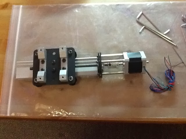
Z axis partially completed
The Z axis spindle carriage and slide rail are put together ... Though I think I may need to adjust or move the nuts for the Z axis threaded rod. The rod does not spin straight and has a slight wobble to it though it does not hit anything when I turn it.


Monday, February 10, 2014
Setting Motor Current
Check out the following link on how to adjust the current on your grblshield.
Clockwise increases current, counter-clockwise decreases current.....


Sunday, February 9, 2014
Pen test

Pen test went very well!!!! I'll write more about my overall findings including an overheating z axis stepper. That's everyone's problem or you might call it my current problem... More to come on this.
More wiring
"


I used 1/4 plastic tubing to protect the wire on one of the y axis stepper motors. The tubing snaps nicely into the extrusion.

Inside the control box

By the way, thanks for the connector son!!! I chose to use a separate connector (see green thing in black box) to isolate / remove any physical stress to the controller board.
Wire guide

I constructed my wire guides from left over clear tubing and a 3 foot long plastic wire wrap. The control wire and wire wrap are all stuffed inside the clear tubing. The wire wrap prevents the tubing and control wire from kinking when moving. This was definitely a wire guide experiment, but I am very happy with the results.
Carriages - Half Done
So I managed to get the V-Wheels and Smooth Idlers mounted on the carriage plates. I decided to thread lock the nuts on everything except the eccentric nuts.

V-Wheels and Smooth Idlers Completed
Well I finally have the V-Wheels and the Smooth Idlers together and they actually went together much easier than I expected. The first picture shows about half of the V-Wheels completed .. I decided to put the first bearing all the V-Wheels first before putting the washer and second bearing, this seemed to work well. One problem I did face was with my dry skin, about half through my thumb started to bleed because I crack the skin open.


Is it square yet???
Just one photo (see below) to get you thinking about squaring the CNC. I can't over emphasize how important this step is! It is the most time consuming step in the build process and guess what. You will need to do it again over the life of the machine. I'm going to put together an in depth article depicting the method I used. This photo is probably a good indication......pun intended. :-)


Belt installation


Helpful note... Slide the belt completely under the idlers and drive. This makes it easer to loop the belt from the two idlers onto the stepper motor drive.
Z Issue is Fixed
I had problems with the lead nut binding and making the screw very hard to turn. Other blogs suggested running the nut back and forth using a drill to turn the screw. That did not work and in fact made it harder to turn! I was about ready to get the correct size tap and re-cut the threads in the lead nut, but decided to look inside the lead nut first. I could not get a photo of the inside but it was packed with debris most likely from the original threading. Running the nut up and down the threaded rod will not clear the problem. I took a small needle with a slight bend and manually cleaned it out. Then I used compressed air for a final cleaning. TADA !!!! It now works like a champ.
Inventory Completed
Inventory of all the parts is now completed .. as shown in the picture, I decided to place most of the parts in empty baby food jars. Each jar is labeled to ensure the parts are not confused.

Ensuring the kit is complete is a little frustrating as not everything which is included in the kit is part of the packing list (the electronics, stepper motors, drill, tools). Additionally, my kit included two bags of parts which are not labeled and not on the parts list (shown below).
I am guessing these are needed to drive the belts for the X and Y axis.

Random assortment of nut, bolts and washers ...

Time to start building!!!
Saturday, February 8, 2014
Z build it and they will come...

Make sure to keep bolts loose when doing this build. Otherwise parts may not line up.

Found out this will not work. I ended up mounting the brass Standoffs on the stepper motor first. Much easer!!!! Also, because the threads are too long for the stepper motor and I didn't want to use a bunch of washers, I put a nut on each standoff first to take up the extra thread. This method has benefits if you need to adjust the tilt of this particular stepper motor.


Don't forget the spring washer like I did. It's not in Shapeoko build diagram but does reference the spring in the text.

Y left and right and terminal strip mount.


Decided to use 3M tape to mount terminal strips. The bolts supplied were too small for the mounting plate requiring multiple size washers.
Idler spacers
Ok don't make this mistake!!! The photo below shows the two washers placed after the spacer. This is incorrect as the hole size in the spacer is much to large to seat against the bearing. The washers should be placed on each side of the spacer to seat properly. The correct placement is shown below...
How to Power up or off
Anyone have any idea the sequence for powering up or off the control board? Arduino first or gshield first?
Electronics testing
As part of the Shapeoko 2 build documentation (http://docs.shapeoko.com), the first thing that is recommended is to test the electronics before you start building the machine. The documentation provides clear instructions on how to connect the different components together though it does not provided a clear understanding of the Y axis wiring. Based on the wiring picture in the documentation it is easy to over look that one of the Y axis stepper motors has the wires switched (The green and black wires are switched). The Y axis has two stepper motors which should spin in opposite directions of each other. When wiring your Y axis stepper motor make sure you have the wiring correct and that the motors are not spinning in the same direction.
I downloaded the Universal G-Code Sender for testing the electronics as this would allow me to control the axis manually. The test of the electronics was good and everything worked as expected. I also ran through the "Hello World" example in build documentation which looked to work correctly.
I downloaded the Universal G-Code Sender for testing the electronics as this would allow me to control the axis manually. The test of the electronics was good and everything worked as expected. I also ran through the "Hello World" example in build documentation which looked to work correctly.

While testing the electronics I noticed that the Z axis stepper motor was vibrating on the table much more than the other axis stepper motors. Unsure if it was the stepper motor of the gShield I swapped the X and Z axis stepper motors ... it was clear then that it was an issue with the gShield. I then adjusted the trim pot for the Z axis (counter clockwise) to reduce the motor current which did lessen the vibration of the stepper motor. I also lessened the motor current for the X axis which made that stepper motor seem to run much smoother. I guess since the Y axis has two stepper motors the default current setting on the gShield was sufficient. As of right not I am not sure if changing the motor current on the X and Z axis will affect the performance of the machine but it did make them seem to run smoother.
The Shapeoko 2 Arrives
After several months of waiting and several shipping delays my Shapeoko 2 machine finally arrived.


Pictures of the promotional items included in my order: Stickers, iron-on patch, starter bits and a t-shirt (pictured above)

Close up of the started bits:

Guess it is time to do a quick inventory and start testing the electronics.
Kit has arrived..... And we're off!
Completed checkout on electronics. Now on to the build...


Note about constructing a control box. Looked at some of the other blogs on Shapeoko 2 regarding building a control box for the CnC. Some examples used 4 pin connectors usually costing $4-$5 dollars. I decided for my build not to go this route as I am concerned about connectors coming loose. In a previous life, while building a completely home brew CnC, one of the connectors came loose and destroyed my controller board. I will post more photos as I go along. In any case here are some photos of initial inventory, Bering build and prep for the next phase. More to come.
Subscribe to:
Posts (Atom)